This guide helps field users identify and resolve common issues causing data transmission failures during pump down.
TABLE OF CONTENTS
- Verify Hardware Setup
- Check Connections and Data Transfer
- PD Indicator Green but Missing Pump Down Data
Step 1: Verify Hardware Setup
Review Hardware Diagrams:
- Ensure the Access Point Power Adapterconnections are correct:
- Ethernet from the Access Point goes into the POE port.
- Ethernet from the Serial to Ethernet Adapter goes into the LAN port.
- Ensure the Access Point Power Adapterconnections are correct:
Inspect Hardware Components:
- Check for damaged equipment, missing components, or bad connections.
- Refer to the next images, Pump Down Hardware or Pump Down Hardware Connection for reference.


Step 2: Check Connections and Data Transfer
Verify Serial to Ethernet Adapter:
- Ensure the TX/RX light indicator is flashing green, confirming data transmission.
- If no lights are flashing:
- Check the power connection to the adapter.
- Ensure the serial port is correctly connected to the pump down computer.
- Verify the setup on the pump down computer is configured to stream data to the adapter’s port.

Ping the Serial to Ethernet Adapter from Dipole Computer:
- Open Command Prompt (search CMD in the Windows search bar).
- Run the command:
- If packets are received: Communication is established.
- If no packets are received:
- Verify the connectivity of the Access Point sending the pump down data.
- Refer to Access Point Troubleshooting Guide.
Step 3: PD Indicator Green but Missing Pump Down Data
1. Check the Dipole Pump Plugin
- Open the plugin and locate the box circled in redto verify if data is being received:
- If numbers are present and constantly changing: Proceed to assign the data.
- If the box is blank or values are static: Proceed to Step 4.

2. Assign the Data
- Identify the index of the desired variable:
- Index numbers appear in the box circled in green and correspond to data positions in the string.
- Match the index to the expected pressure or rate:
- Example: If Index 6 shows a value of 5, this represents the pressure at that moment.
- Enter the index into the relevant fields:
- Use the red-circled box for pressure.
- Use the blue-circled box for rate.
- Special Cases:
- If rate already totals all pumps: Only use the Pump 1 slot.
- For unique rate/pressure per pump: Assign indices individually, the system will average the pressure and sum the rates.

3. Data is Present but Only Zero Index Appears
- Check the Division Characterin the plugin:
- The default is a comma. If the data uses a different separator (e.g., space, period), update the Division Character field (circled in red).
- For space separators:
- Delete the default.
- Hit space, then Enter to save.
- Once indexed correctly, return to Assign the Data.

4. No Values or Static Values
- Revisit Step 2: Check Connections and Data Transfer to ensure hardware and connections are functioning.
- Verify the Port and Host IPin the plugin:
- Host IP: 10.0.0.2
- Port: 90
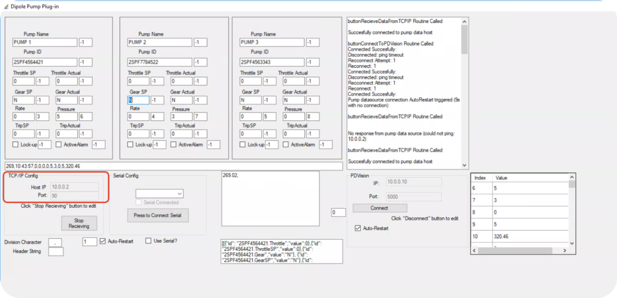
- Ensure the plugin is set to receive and send data:
- In the PDVision section, click Connect if available.
- In the TCP/IP Config section, click Start Receiving.

Important Safety Notes:
- Always verify hardware connections and ensure all cables are securely connected.
- Avoid making changes to the system unless you have verified network and hardware status.
Was this article helpful?
That’s Great!
Thank you for your feedback
Sorry! We couldn't be helpful
Thank you for your feedback
Feedback sent
We appreciate your effort and will try to fix the article